Sandia National Laboratories: Battery Lead Fatigue Analysis
A comprehensive finite element analysis study focused on predicting and mitigating fatigue failure in battery lead connections under cyclic mechanical loading conditions.
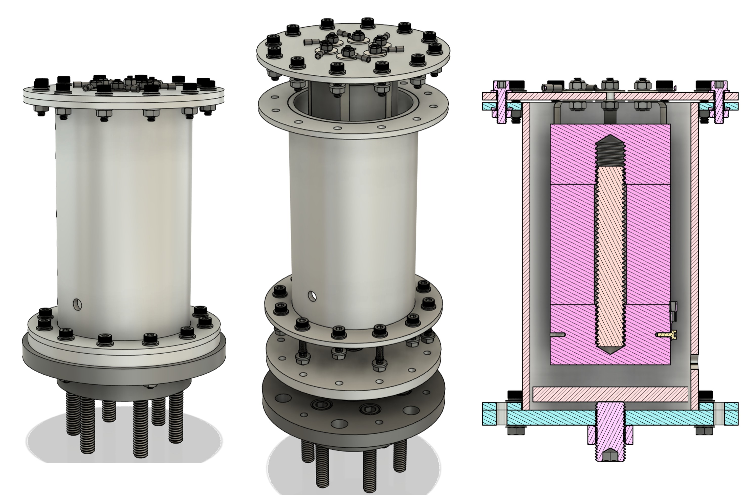
3D isometric view of the final iteration of the thermal battery test fixture assembly.
Problem Statement
A known failure mechanism of thermal batteries is fatigue cracking of the internal electrical leads that connect the electrochemical stack to the terminals in the header. In order to properly assess the viability of new lead designs, a parametrized finite element model in ANSYS, a fatigue material model, and a simplified experimental setup is needed to close the knowledge gaps around the impact of design choices.
Deliverables
- Deliver a fully parametrized ANSYS model of battery geometry, lead geometry, lead materials, and stress/vibration analysis for relevant axes.
- Design of an experimental setup to rapidly collect validation data. The faster the data, the better.
- A prototype of the experimental test setup.
The Engineering Process
To begin, my team and I conducted an extensive literature review in thermal battery technology, fatigue failure modes, vibration testing standards such as MIL-STD-810H, electrodynamic shaker technology, and more. As a result of our research, we wanted to approximate the actual thermal battery conditions as closely as possible in our fixture design (neglecting the thermal conditions of the battery). This process included mimicking the exact dimensions of the actual battery as well as the boundary conditions (BC) the lead experiences. The internal lead is subjected to compressive stresses due to the changing axial/radial pressure inside the battery case.
- The V1 fixture was successful in mimicking the static BC of the lead.
- V1 allowed for up to 6 independent leads to be tested simultaneously.
- It enabled the fixture to be tested in both x and y axes.
- The split casing design was chosen in V2 to allow for easier access to internal components.
- Featured a removable header and base.
- Incorporated a 3 piece slug geometry to mimic the electrochemical stack.
- V3 returned to a unibody case design, since the split-casing feature increased the manufacturing time and cost, with little additional functional benefit.
- V3 featured enlarged mounting holes to provide larger FoS during vibration testing.
- Incorporated an adjustable internal pressure system to vary the pre-stress the lead experiences inside the battery fixture.
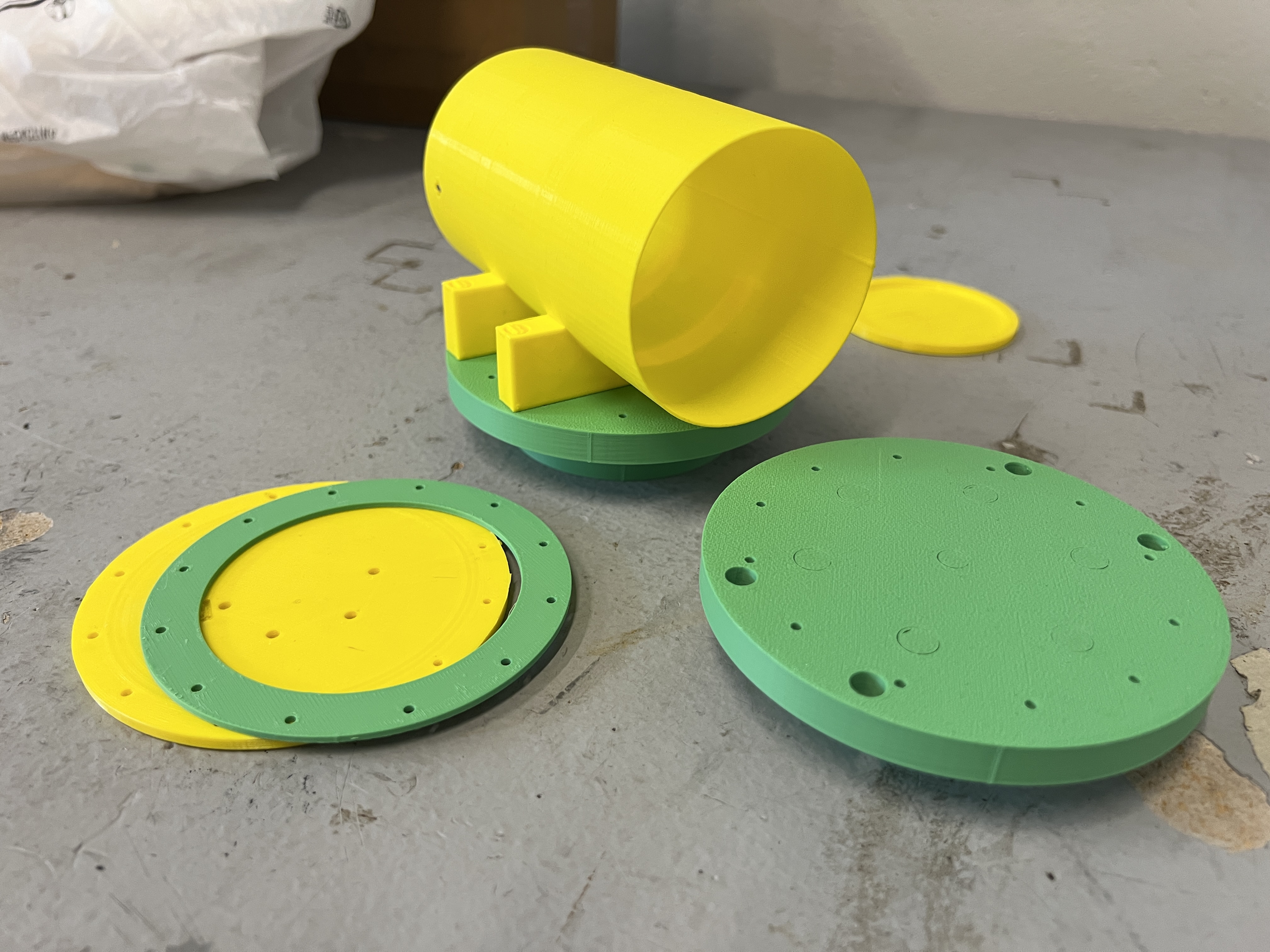
Image of the V1 test fixture prototype. This design includes a unibody casing and two sets of flanges to mount to an electrodynamic shaker for bi-axial vibration testing.
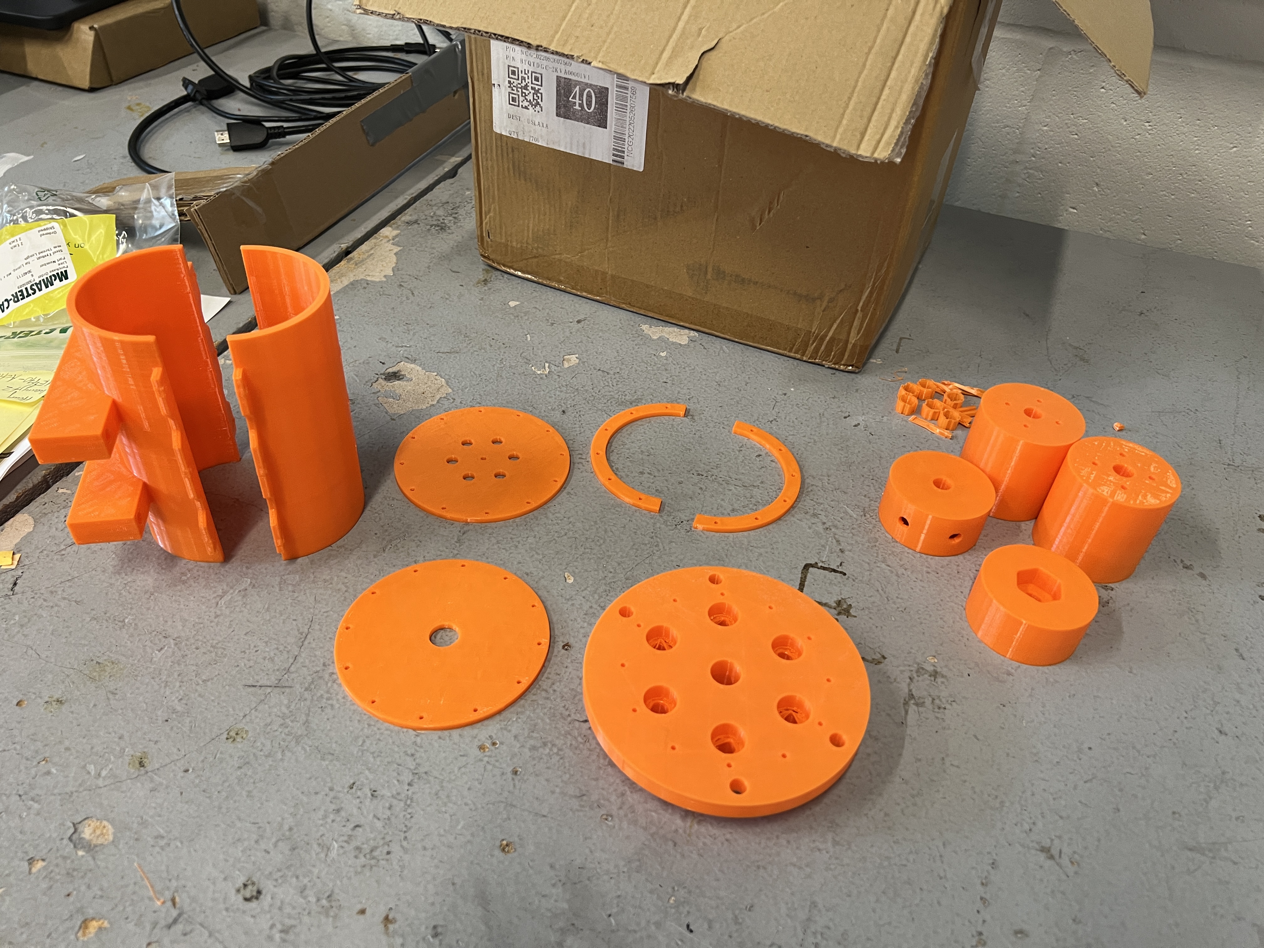
Image of the V2 test fixture prototype. This is the most complex design that features a clamshell casing, bi-axial shaker mounts, and adjustable pressure system.
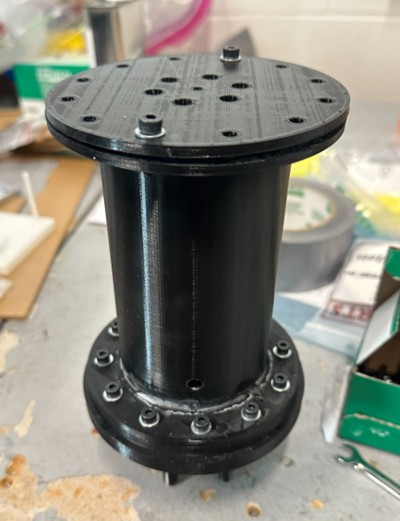
Image of the V3 test fixture prototype. It includes a unibody case, single axis shaker mounts, vibrometer access holes, and adjustable pressure system.
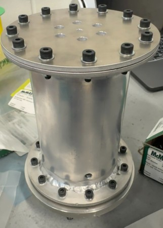
Image of the final CNC machined fixture, comprised of 6061 T6 Aluminum and 1018 Steel components.
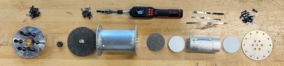
An exploded view of the entire fixture assembly, featuring a lb-inch torque screwdriver for calibration.
Fatigue Detection Method: "Glitch Detection"
To measure the fatigue life of the electrical leads during sinusoidal vibration testing, we implemented a failure detection method known as "glitch detection."
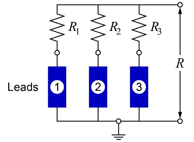
Circuit schematic for the glitch detection circuit we used to detect fatigue failure in the battery electrical leads.
The total resistance of the glitch detection network can be calculated since the electrical leads are connected in parallel.
Series Resistance Network
$$ R_{eq} = R_1 + R_2 + R_3 + \dots + R_n \label{eq:series} $$Parallel Resistance Network
$$ \frac{1}{R_{eq}} = \frac{1}{R_1} + \frac{1}{R_2} + \frac{1}{R_3} + \dots + \frac{1}{R_n} \label{eq:parallel} $$When a lead experiences microcracking due to mechanical fatigue, and ultimately cracks- the equivalent resistance of the glitch detection circuit will change. Measuring this change in resistance allows us to detect fatigue failure, by simply connecting an oscilloscope or a Digital Multimeter (DMM) across the resistor network.
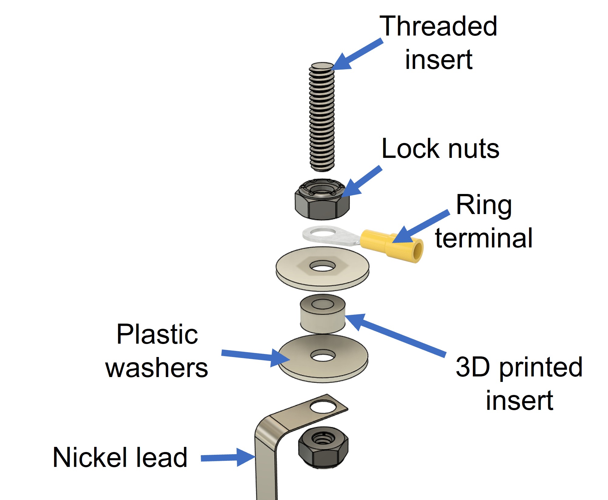
An exploded view of the glitch detection mechanical connection at the terminal in the header.
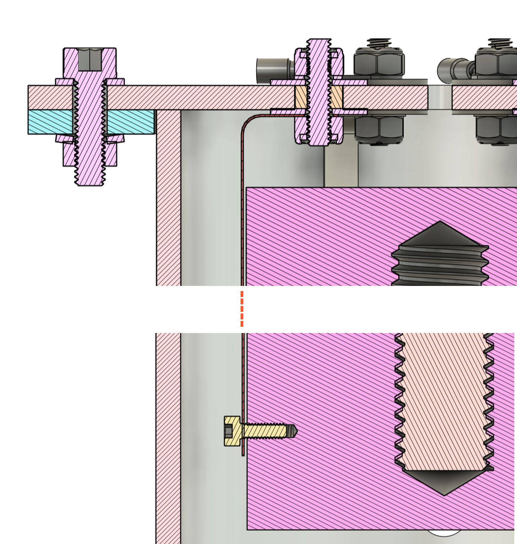
A cross sectional view of the glitch detection mechanical connection, within the entire fixture assembly.
The mechanical connection shown in the two above images was the simplest and most reliable connection, enabling the system to be treated as a single input single output (SISO) system. This drastically simplified our setup procedure and necessary equipment compared to previous proposed methods. Now, we can directly measure the resistance in the fixture as a direct indication of fatigue failure of any of the leads- while still maintaining information on which lead failed.
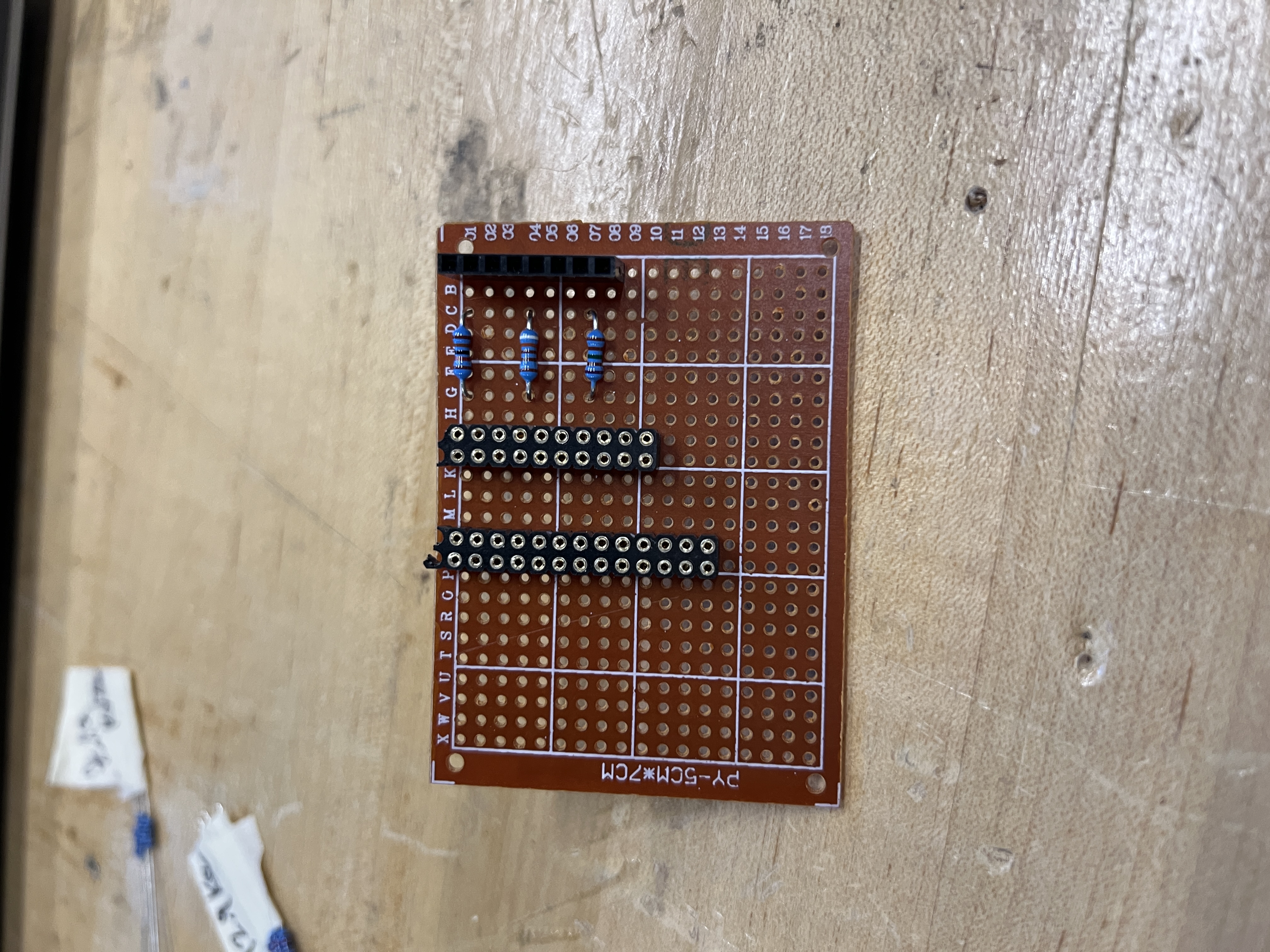
Image of the perforated circuit board that I soldered, used for verifying glitch detection.
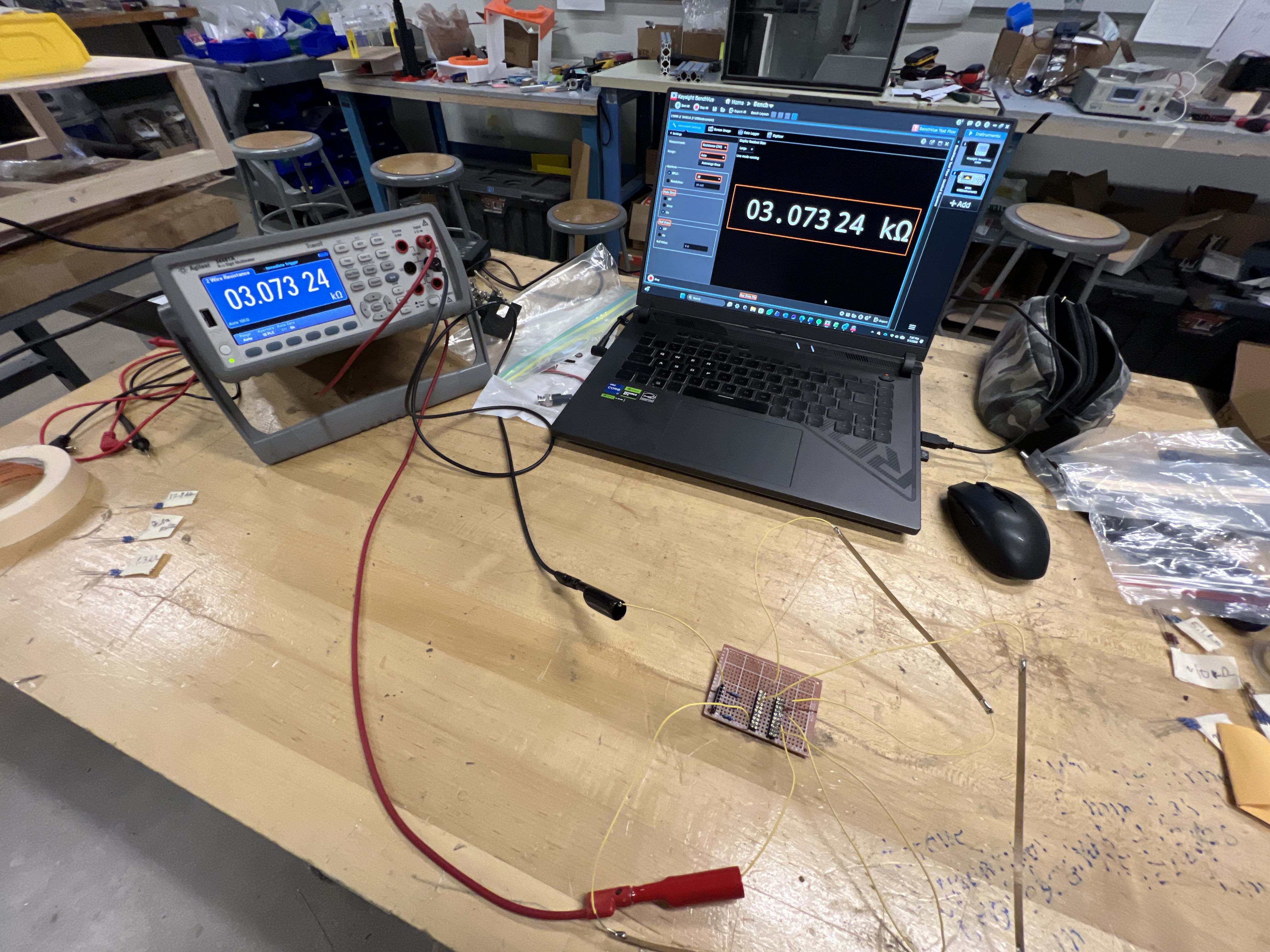
The test setup that was used for testing the glitch detection circuits, showing the perf board, respective nickel lead connections, Agilent Digital Multimeter (DMM), and a laptop running BenchVue for data acquisition (DAQ).
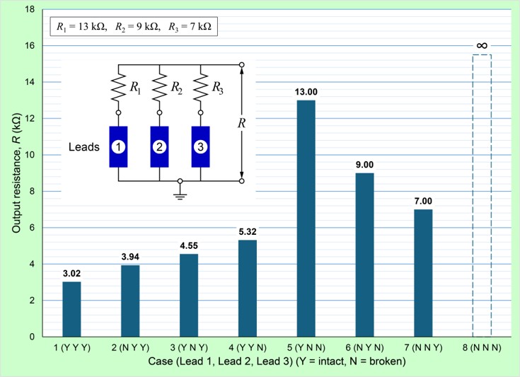
The above graph displays the output resistance of the network with respect to if fatigue failure has occurred in any of the leads.
The glitch detection verification testing showed less than 3% error in our predicted resistance values. This confirms that glitch detection is a viable method for detecting fatigue failure in the battery electrical leads, and can be used for future research and development.
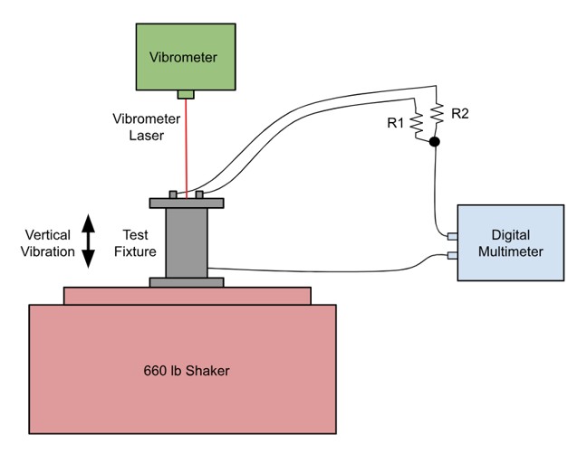
A system schematic of the entire fixture test setup.
The above schematic illustrates how the glitch detection circuit is integrated into the fixture, as well as how the entire vibration test is setup. A vibrometer is utilized for measuring the kinematics of the internal battery core.
ANSYS Finite Element Analysis (FEA)
Finite element analysis (FEA) was utilized to model and predict the fatigue life of the leads and resonant frequencies of the battery system. The resonant frequency is when the battery is most likely to experience fatigue failure. Once resonance was identified, this would allow the team to perform sinusoidal vibration testing with our physical setup, and measure the fatigue life of the electrical leads using the method of glitch detection. Due to time and equipment constraints, the team was unable to perform physical vibration testing.
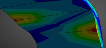
FEA results showing stress distribution in the bend of one of the leads. The lead is experiencing stresses from both tension (red) and compression (blue) in the bend.
To accurately model the axial insulation of the battery in ANSYS, the team performed axial compression tests using a UTM. Specifically, the Young's Modulus of two different materials were experimentally determined. The stress-strain curve highlights the non-linear behavior of both materials under compressive stresses.
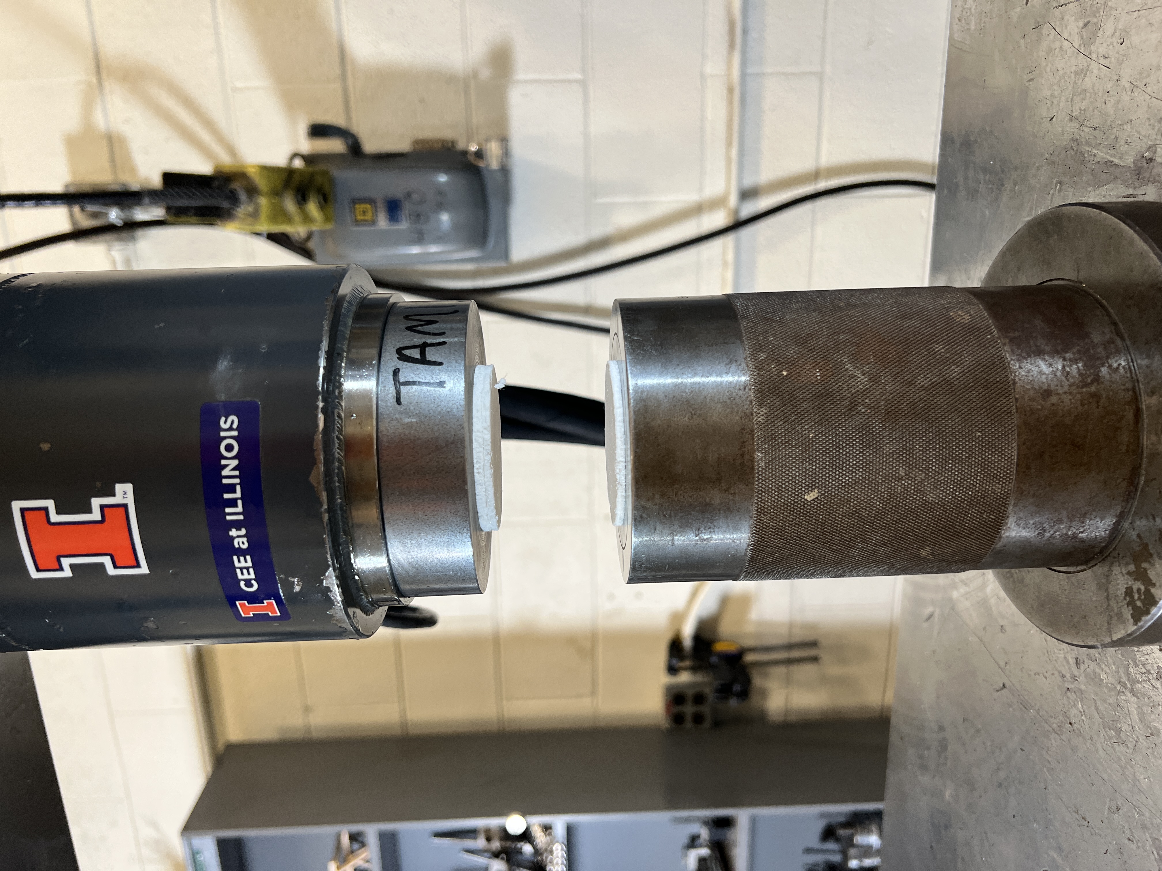
Axial compression testing of sample battery axial insulation in a UTM.
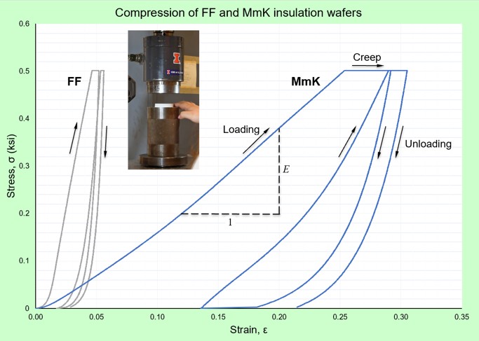
Stress-strain curve for two axial insulation materials, based on in-lab compression testing data.
Outcome
- Created parameterized ANSYS FEA model of both replica thermal battery and fixture design for future design iterations and material studies.
- Performed ANSYS FEA studies (static structural, modal, harmonic response) for both replica battery and fixture assemblies, with resonance occurring at approximately the same frequencies. (Details withheld per NDA)
- Satisfied the project deliverables by executing two sinusoidal sweeps over the specified frequency ranges. (Details withheld per NDA)
- Identified critical stress concentration regions and recommended localized geometry modifications.
- Note: Some quantitative results have been omitted to satisfy NDA requirements.
Contributions
- Led the fixture design subteam in designing a reusable and scalable vibration testing fixture for thermal battery electrical leads, in accordance with the most recent vibration testing standards (MIL-STD-810H).
- Executed benchtop DC resistance and AC impedance testing of the thermal battery leads to establish expected resistance values for use in the glitch detection circuit.
- Conducted axial compression testing of various battery insulation material in a universal testing machine (UTM), inputting those results into the ANSYS FEA model.
- Spearheaded the technical communication between the fixture design team and the machine shop- ensuring that design for manufacturing (DFM) principles were adhered- resulting in minimum cost and lead times.